 Voltage regulation, tube style
High voltage indeed
The Meter on my Heathkit HW 101 stopped displaying ALC (dropped down to the negative stop). So, I opened up the old rig to have a look. I found that the B+ voltage was reading 33 volts higher at one of the test points than it should. Ultimately that voltage didn't turn out to be the problem with the alc meter instead the meter switch had become dirty and needed to be cleaned. But in the process it got me to studying the way voltage is regulated in the Heathkit and I learned a bit about voltage regulation tubes like the OA2 used by Heathkit.
 |
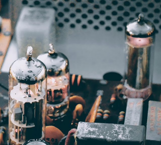
| OA2 tube |
 |
| OA2 in action at the right rear of the Audio board, notice the glowing gas inside |
More Glow...
The OA 2 is actually not a vacuum tube it contains a gas that ionizes and in the process of ionization acts as a voltage regulator. In a vacuum tube, if you see glowing gas inside the tube that means it's leaking and has become "gassy", that's a bad thing. In the case of a gas filled tube like an OA2 you expect to see glowing gas and if you do not, then there's a problem.
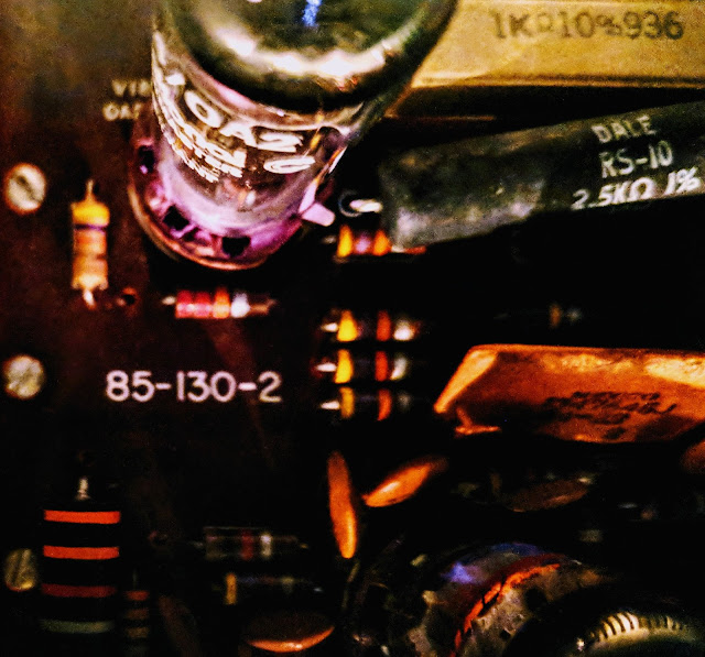
In this case The OA2 regulates voltage to 150 volts and current is limited by the two high-wattage resistors connected in circuit to that tube (seen beside the OA2 in the photo above). Those resistors are dissipating a lot of heat. I measured over 300F degrees with my IR temperature gauge (ouch).
I emailed one of the members of my local club, Joe WA4GIR to ask about tube testing and he sent me the following, which he gave me permission to post:
 |
| Look at the pretty violet glowing gas in the OA2 |
The OA 2 is actually not a vacuum tube it contains a gas that ionizes and in the process of ionization acts as a voltage regulator. In a vacuum tube, if you see glowing gas inside the tube that means it's leaking and has become "gassy", that's a bad thing. In the case of a gas filled tube like an OA2 you expect to see glowing gas and if you do not, then there's a problem.
In this case The OA2 regulates voltage to 150 volts and current is limited by the two high-wattage resistors connected in circuit to that tube (seen beside the OA2 in the photo above). Those resistors are dissipating a lot of heat. I measured over 300F degrees with my IR temperature gauge (ouch).
Tube Testing without a tube tester?
The lack of a tube tester is not a limitation. You can tell a lot about a tube test by looking at the voltages in the circuit. If the filament goes out, the tube is dark and does not conduct. That one is pretty obvious. If the tube cathode loses it's ability to emit electrons, the voltages dropped across the cathode resistor and any resistors in the plate or screen grid circuits will change (the voltage drops across those resistances will drop). A good tube tester will measure the ability of the tube to vary the plate current for changes in grid voltage, and you can see this with a scope by looking at the AC voltages on those elements, at least for the audio circuitry. Probably not so much for the RF circuits as you are affecting the circuit when you probe it. The best way to check for a suspect tube is to replace it with another. I have 0A2's new in the box. I may have the other tubes pulled from radios but it takes longer to look through those as sometimes the numbers are hard to read. Hint. to bring out a faded number, rub it on the hair on the back of your neck-- better if it's oily.A lot of resistors in old tube-type radios were 20% tolerance so don't expect the voltages to be that precise. Tube rigs had much more variability than modern solid state circuits. For the unregulated voltages, the precise voltage will depend component tolerances, tube health, and line voltage. The line voltage here is about 125 when where I lived in Raleigh it was around 110. You can do the percentages but that alone will account for some of the variation you might see. I don't think that any of your tubes were damaged by overvoltage. If they are drawing too much current, they will get hot, and in severe cases, the plates will glow red. That's a concern. Much less than that, the life might be reduced but I don't think you will see any short term effect. When I've run tubes too hot, you might see signs of the tube going gassy, which is indicated by a blue low in the space inside the tube that is supposed to be a vacuum.If you want to see the plates of a tube glow red, operate the final mistuned so it is drawing too much current. They will glow red, haha.The voltages out of the 0A2 are different -- they should be held pretty closely to 150V. I don't know the exact tolerance. It might be a few percent. So in your radio, 150V supply and any that are derived from it are the only ones that would have a tighter tolerance. The 0A2 has an operating current range of 5 to 30ma, and an operating voltage of 150V. The supply voltage should be at least 185V to get the tube to "fire" but once "on", the voltage feeding will drop to the 150V level and be regulated there by the action of the tube which causes the voltage drop across to change (like zener diode regulators). The regulation comes from the fact that a very small increase in the voltage across the tube results in a significant increase in the current so the resistor values are chosen so that the current through the tube remain in the 5 to 30ma range as the input voltage and the current draw of the regulated circuits varies for whatever reason. Remember the current draw when you first turn on the rig will be low because the tubes don't conduct until the cathode gets heated so the designer must account for that in the selection of the input resistors to that circuit.
More to learn about hollow state
As a young-ish ham I certainly have a lot to learn about old tube radios but I'm enjoying the journey. Just the thought of transistors operating by thermionic emission, tossing their electrons across empty space, being attracted to a plate with more positive voltage is fascinating to contemplate.
That's all for now
So lower your power... or at least regulate it with a OA2... and raise your expectations
73
Richard, AA4OO


